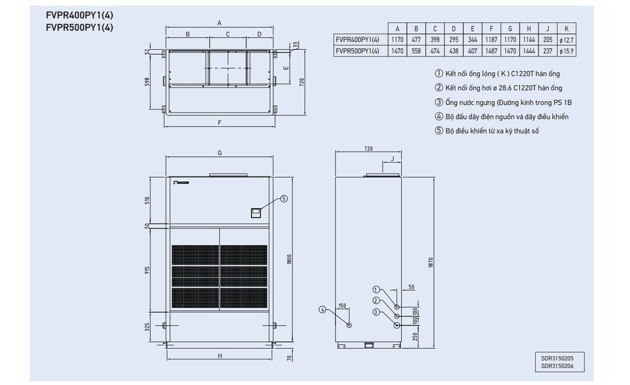
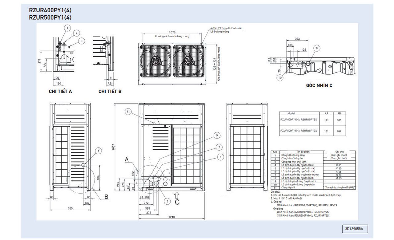
Dimensions (unit: mm)
Daikin indoor unit - Duct connection
Daikin outdoor unit - Duct connection
Design flexibility
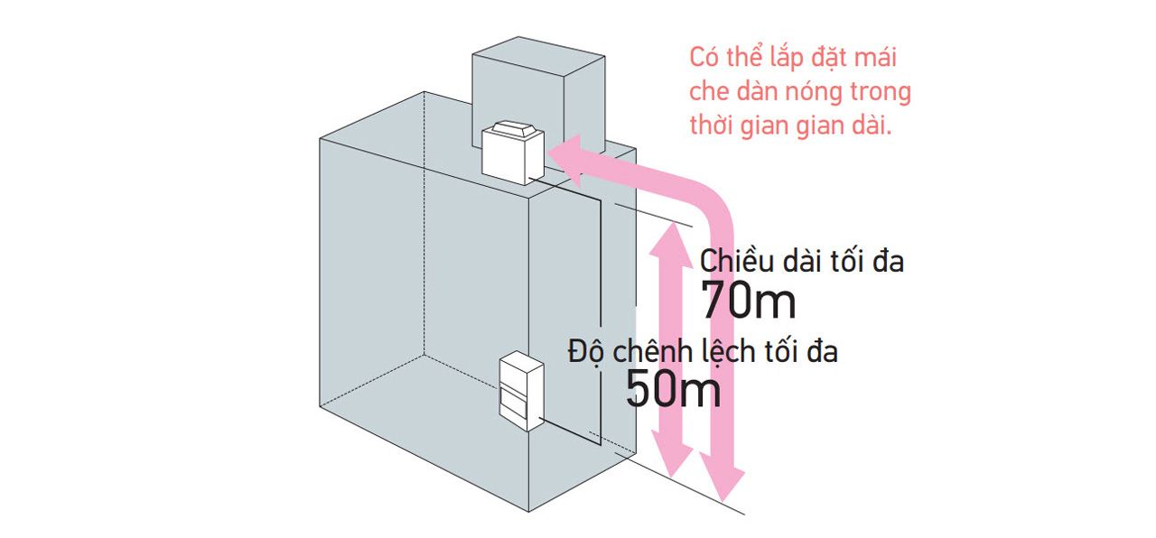
Designed for long refrigerant piping
70 m maximum length and 50 m maximum level difference to cover medium- and large-scale building needs.
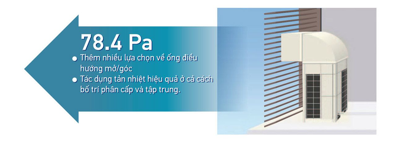
High external static pressure
The outdoor unit has been achieved high external static pressure up to 78.4 Pa, ensuring the efficient Display of air filter cleaning times and self-inspection function for simple maintenance. heat dissipation and stable operation of equipment in either hierarchical or intensive arrangement
Nighttime quiet operation function
The nighttime quiet operation function automatically suppresses the nighttime operating sound by reducing operation capacity to maintain the quiet environment of the neighborhood. Three selectable modes are available depending on the required level.
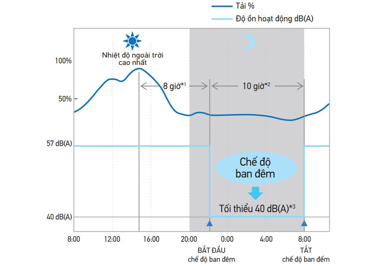
*1. Initial setting is 8 hours. Can be selected from 6, 8 and 10 hours.
*2. Initial setting is 9 hours. Can be selected from 8, 9 and 10 hours.
*3. In case of RZUR250PY1(4).
Notes
- This function is available in setting at site.
- The operating sound in quiet operation mode is the actual value measured by our company.
- The relationship of outdoor temperature (load) and time shown above is just an example.
Reliability
Backup operation function

Centralized management system extension
Centralized management can integrate with D-BACS system with high speed data transfer. Centralized control is now available when using with Inverter packaged air conditioners. The outdoor unit has been achieved high external static pressure up to 78.4 Pa, ensuring the efficient Display of air filter cleaning times and self-inspection function for simple maintenance.

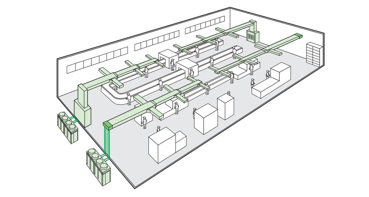
Air blow via connected ducts
- Comfortable air conditioning of the entire factory by connecting a blow duct at the top of the indoor unit. DUCT TYPE
Note: Ducts to be procured locally.
Extended operation range up to 49°C

Note: When outdoor temperature falls below 10℃, the thermostat shuts OFF, the outdoor unit stops, and operation switches from cooling to fan operation
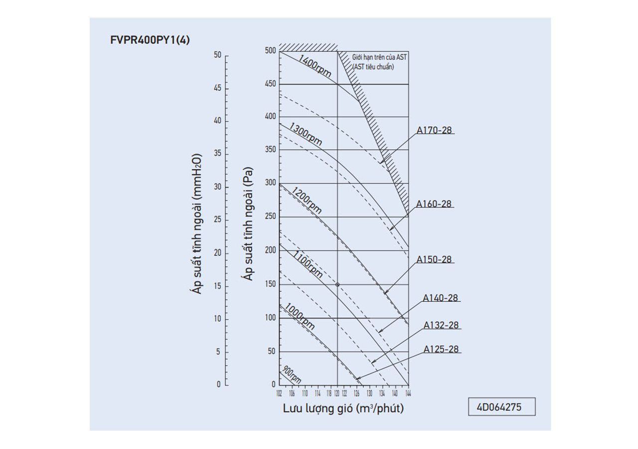
Fan performance
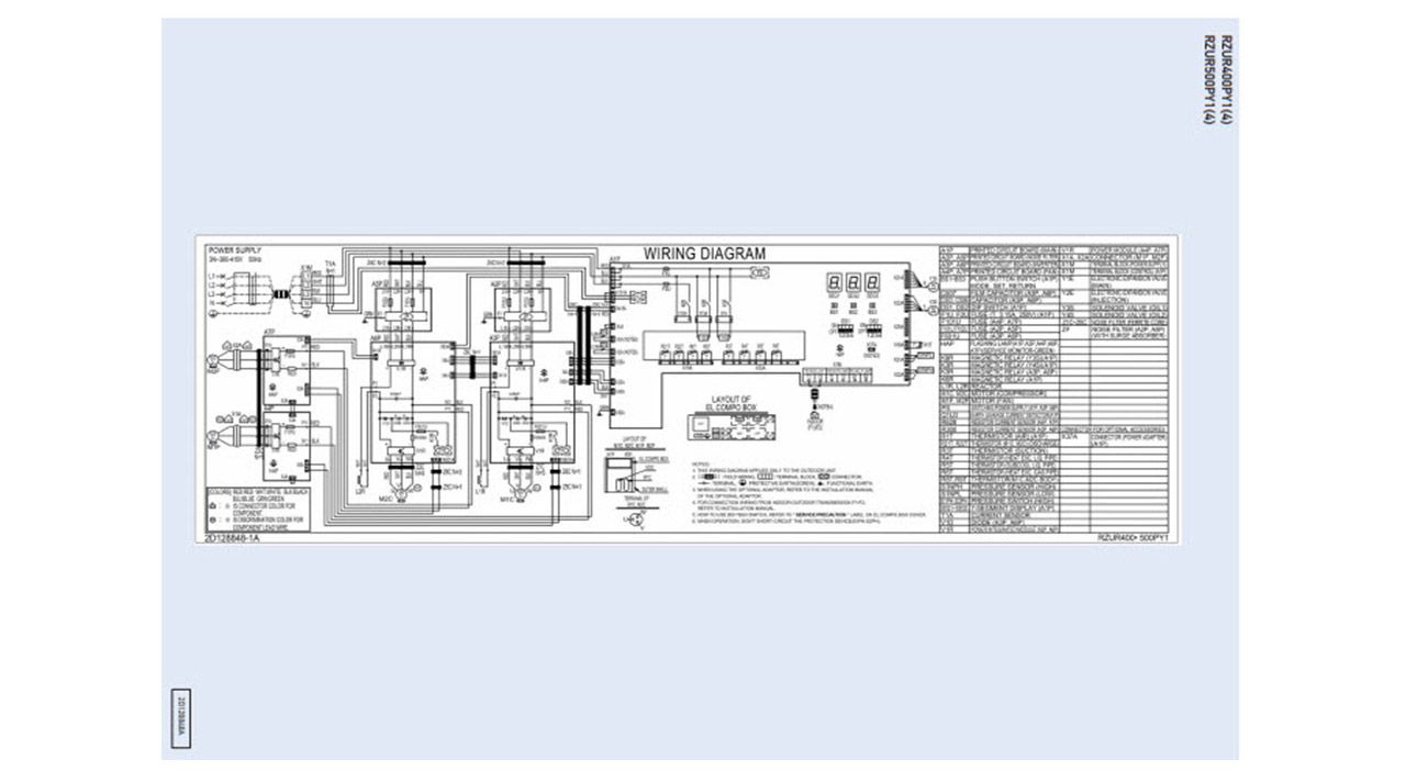
Wiring Diagram of the outdoor unit
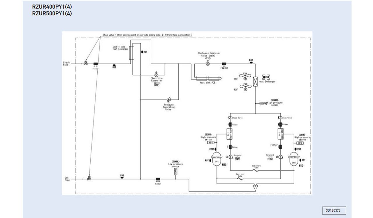
Pipeline Diagram of the outdoor unit
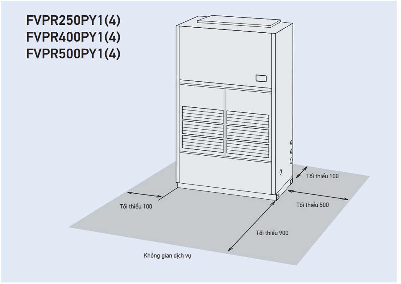
Space required for indoor unit installation (Unit:mm)
Space required for outdoor unit installation (unit:mm)
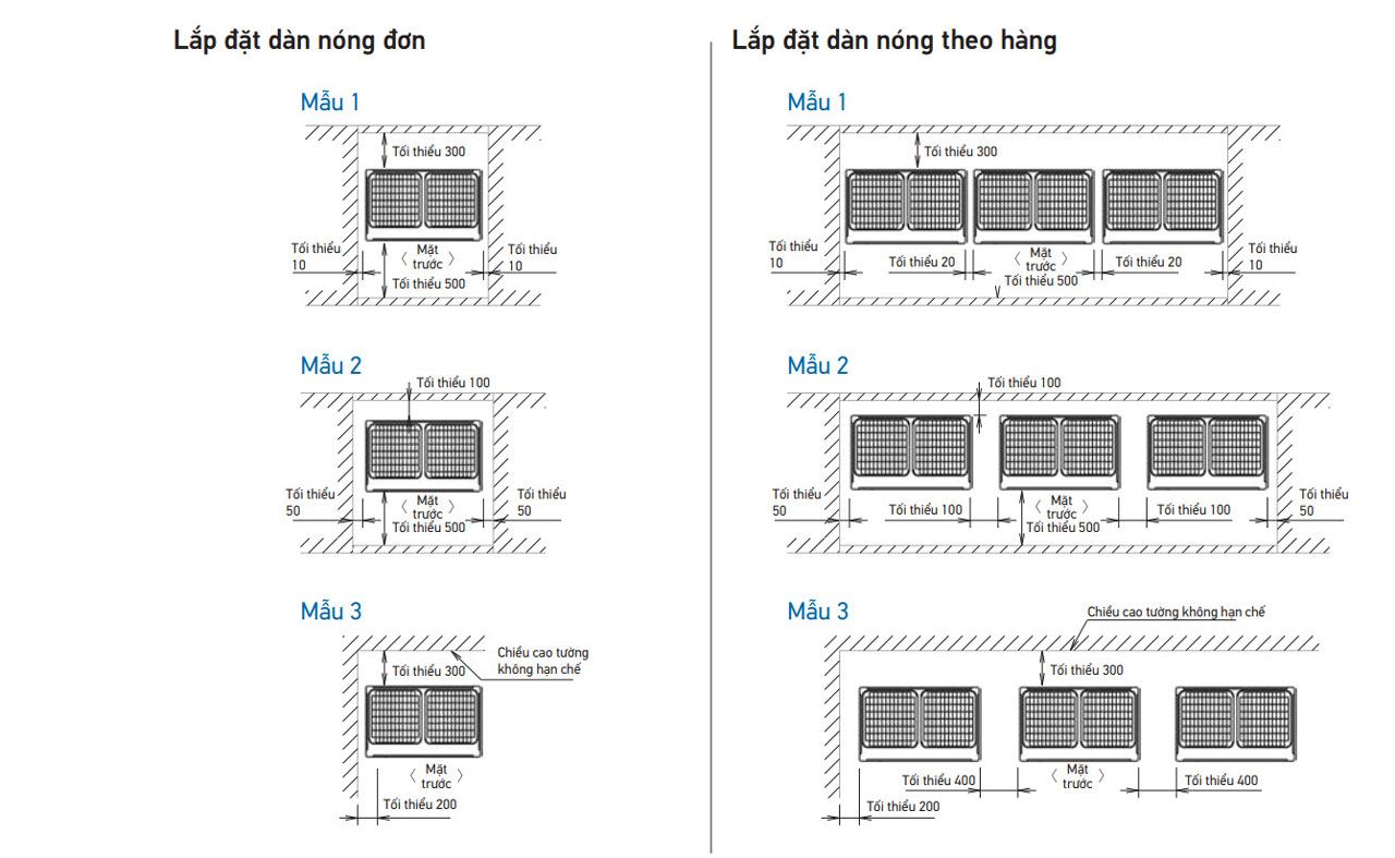
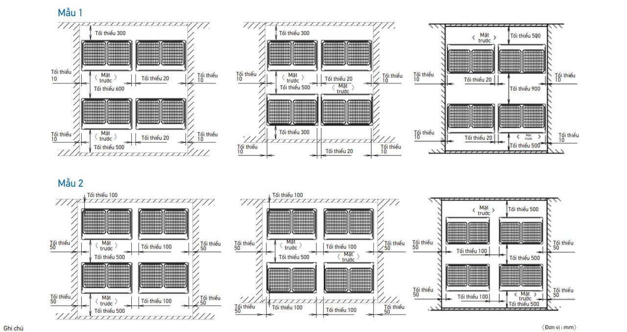
1. Height of the wall in the case of Models 1 and 2:
Front: 1500 mm
Suction side: 500 mm
Side view: Unlimited height
The installation space shown in this drawing is based on cooling operation at an outdoor air temperature of 35 degrees.
When the outdoor air temperature exceeds 35 degrees, or the load exceeds the maximum capacity due to the immense heat load generated by the entire outdoor unit, the suction side space is larger than the space shown in this drawing.
2. If the above wall height is exceeded, then h2/2 and h1/2 should be added to the front and side suction service areas, respectively, as shown in the figure to the right.
3. When installing, the most suitable equipment should select from the models shown above to get the best fit in the available space, always keeping in mind that enough space should be left for one person to pass through between the appliance and the wall allowing air to circulate freely.
4. Units should be installed to leave enough space in front for on-site refrigerant piping to be comfortable.
(If more devices are installed than are provided in the models above, your layout should consider the possibility of a short circuit.)
Specifications
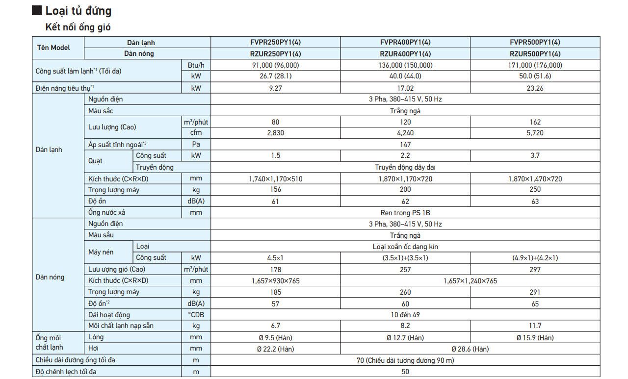
Note :
*1. Indoor temp.: 27°CDB, 19°CWB / outdoor temp.: 35°CDB / Equivalent piping length: 7.5 m, level difference: 0 m.
*2. Anechoic chamber conversion value, measured at a point 1 m in front of the unit at a height of 1.5 m.
During actual operation, these values are normally somewhat higher as a result of ambient conditions and oil recovery mode.
When there is concern for noise the surrounding area such as residences, we recommend investigating the installation location and taking soundproofing measures.
*3. The value is the external static pressure with standard pulley
